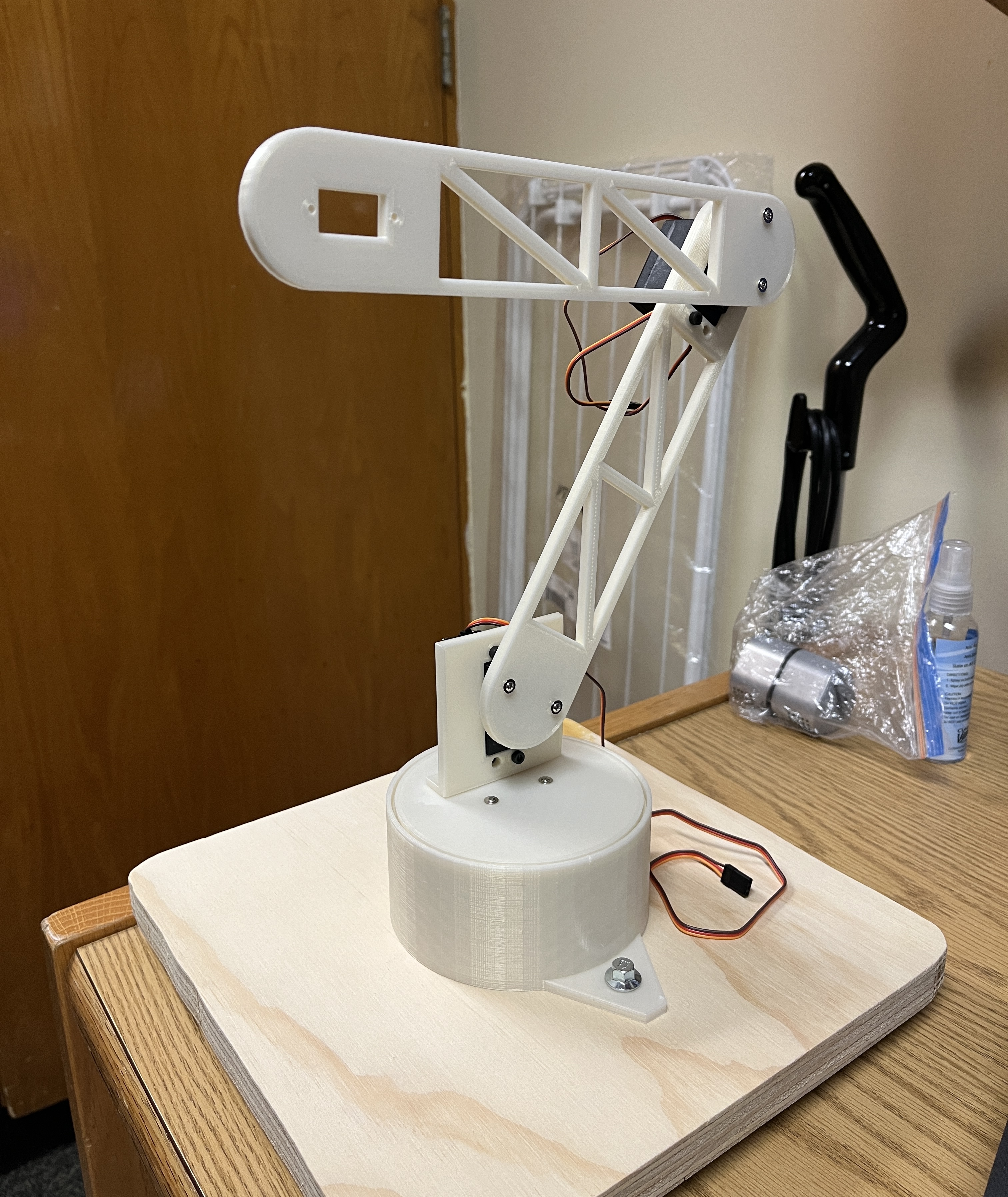
Articulated Robot
Oct 2023—March 2024
Skills and Technologies:
SolidWorks, Project Planning, Mechanical Design, Arduino, Servos, C++

Assembled articulated arm
- Designed a 3 degrees of freedom articulated robot in SolidWorks with one servo mounted at the base and two used for the joints
- Programmed the arm to mimic the movements of the user’s hand, using computer vision to recognize when a user specified hand gesture is displayed
- Used inverse kinematics to convert the location of the user’s hand and size of the bounding box from the camera to angles and PWM values for the servos to mimic, moving the arm’s position to a specific location
- Wired the servo motors to an Arduino Uno using a PCA9685 PWM motor controller board and used I2C communication to send data from the camera
Goal: design a 3 degree-of-freedom articulated robot that could mimic the user's hand movements
This project was started during my first semester of university. I wanted to challenge myself with a project that required mechanical design and programming. An articulated robot was something that came to mind and I began researching electronics and how to wire it all together.
The articulated robot was designed in SolidWorks. I printed it out of PLA filament and assembled using appropriate fasteners. Servo motors were integrated into the design as a direct drive for each degree of freedom. The 3D printed parts were designed with weight saving holes to assist the motors with having the required torque.
An Arduino Uno R4 was used as the microcontroller for the project. A servo motor driver board was used to control the communication between the Arduino and the servos using PWM. I2C protocal was used for communication between the Arduino and a computer vision sensor. Using the sensor I was able to program the articulated robot to follow the movements of the user's hand by training it to recognize a specific user gesture, which indicates that the user wants the robot to mimic their movement. The bounding box that is drawn around the user's hand is converted to a point in 3D space by using the position of the box and the size of the box.
This video demonstrates the use of a specific gesture to inform the robot to follow the user's movements and it also shows the robot following the vertical movements of the user's hand.
This video demonstrates 2 degrees of freedom using inverse kinematics to calculate motor PWM values.
The x-location and y-location of the bounding box translated to a point on a 2D plane, but the height of the bounding box was correlated to how close the user's hand was to the camera. This allowed for a depth value to be calculated for the robot by using the max reach of the robot as the bounding box taking up the camera's entire FOV, and a height of 1 pixel as being directly on top of the robot. These values allowed the robot to stay within a tolerance of about 85% of joint 2's range as outside of this range could cause issues with moments and over torquing the motor. Inverse kinematics was used to calculate ideal angles and PWM values for the motors, based on the values from the bounding box.
This video demonstrates the full 3 degrees of freedom the robot is capable of.
After completing this project, there are some aspects that I would change or work on imrpoving for future iterations. The first would be increasing the possible payload size by switching the servos out for models that have a greater torque rating. I would also work on smoothing the PWM changes so there is not as much stuttering while the arm moves or is idle. A challenge for myself would be to create a custom pcb for this project that would allow me to learn about various protocals as well as pcb schematics. A second challenge would be programming my own object detection model for greater adaptability to the needs of the project, rather than relying on what is commercially avaialble through the sensor.