Fixed-Wing Airframe
June 2024—November 2024
Student Design Team Project
Skills and Technologies:
SolidWorks, FEA, Ansys Fluent, Machining, Project Management, Integration
- Designed an airframe to support a 5 kg, 1.7 meter wingspan fixed‐wing plane capable of changing wings and empennages for research and development, analyzing different airfoils, chord lengths, and control surfaces
- Conducted FEA simulations, validating results with hand‐calculations for the wing spars and tail spar
- Designed cases for electronics including ELRS receivers, a video transmitter, an ESC, and a rangefinder and desgined a mounting bracket for the motor and FPV camera
- Organized a calculator to assist team members with design decisions regarding motor selection, angle of attack, aspect ratio, stall speed, and many other flight characteristics as well as determining geometries of control surfaces based off necessary moment arms for the plane’s geometries
- Machined parts on a mill and a lathe and used a waterjet to cut out sheet metal parts allowing for quick assembly
Goal: design a fixed-wing aircraft that can be used for research and development for future knowledge when designing a VTOL aircraft
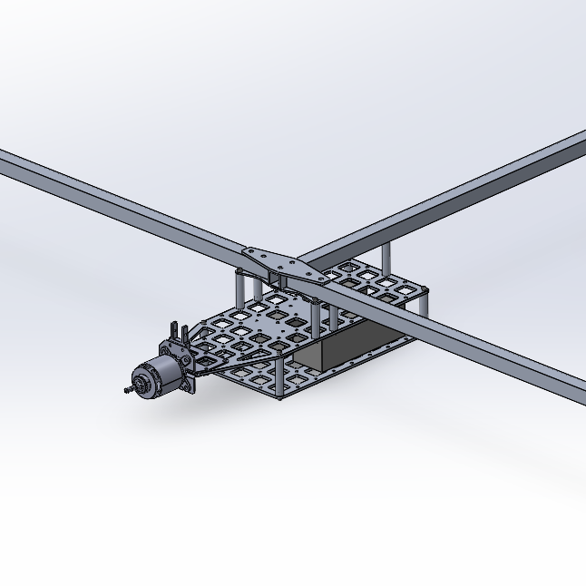
Figure 1: Assembled fixed-wing airframe.
This project is a part of a design team project to design a 5 kg fixed-wing aircraft. The fixed-wing aircraft is dedicated for research and development, allowing the team to learn about the design and fabrication for fixed-wings before we begin to tackle designing a VTOL hybrid aircraft. I was the designer for the airframe of the plane, which included plates for mounting electronics and batteries to, mounting methods for the motor, mounting methods for the wing spars and tail boom, and conducting FEA studies on the spars.
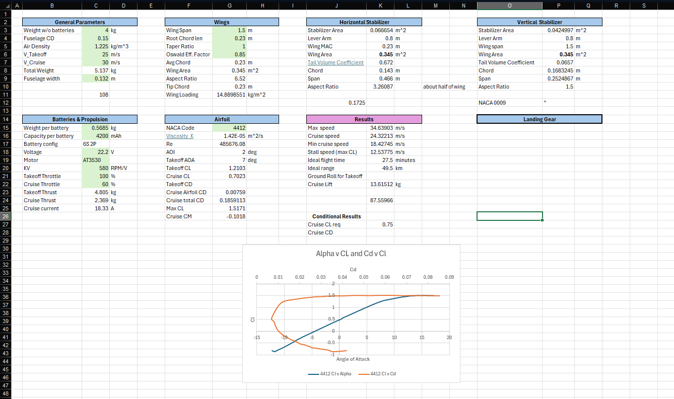
As a project manager for this project, I also co-led the research and development phase for this aircraft. To assist future members in making design decisions, I assisted in creating a calculator for basic calculations dedicated for fixed-wings, seen in Figure 2. Users input the mass of the aircraft, ideal takeoff and cruise velocities, wing span, and chord length. Combining this information with a NACA airfoil code, information about lift, stall speed, wing loading, and various flight characteristics are able to be seen. Battery information and motor specifications can also be inputted to give a rough estimate of flight time. These calculations are able to give a starting point for members when beginning to design the fixed-wing. Other members added in calcualtions for control surfaces and the horizontal and vertical stabilizers.

Figure 2: Fixed-wing calculator to assist team members in design decisions.
This design for the airframe was chosen to be sturdy enough to hold the weight of a 6S battery and support the moment arms created by the wings. While a balsa frame could have been used, the team decided to have the frame carry all of the load, rather than the fuselage taking some on as well. Because this aircraft is dedicated for research and development, having a frame that could be used regardless of the shape of the fuselage or wings was important.
To begin, the airframe is made of two 8GA aluminum plates that are attached to one another by aluminum standoffs. The plates were cut on a water jet and the standoffs were made on a lathe. A standard mounting pattern of 30.5 mm x 30.5 mm was used on the plates. This mounting pattern is common for hobbyist electronics and is what the team uses internally. This allows cases for PCBs to be easily mocked up and offers an opportunity for the electronics to be mounted directly to the frame by using grommets or standoffs. The aluminum standoffs that hold the plates together are threaded for M3 screws. Similar standoffs are used to hold the guessets that sandwich the wing spars and tailbooms, ensuring they are held tightly.
The mounting method for the spars was chosen to allow for simple fabrication and to allow the wings to be taken off often when transporting the drone. Modeling the wing as a cantilever beam allows for the proper clamping method to be designed and ensuring enough force is applied through the gussets. With back of the napkin calculations, a total of 460 N would need to be applied where the wings are mounted to ensure there is enough force to withstand, the load of wing. The wing was estimated to have a load of 25 N, which is approximately half the force from the wings while the fixed-wing is cruising. To make sure there was a higher capacity when the fixed-wing is climbing altitude, 80 N was used per wing. A safety factor of approximately 3. These calculations led the team to determining two M5 bolts with gussets would be sufficient.

Figure 3: CAD of mounting method for spars and tail boom.
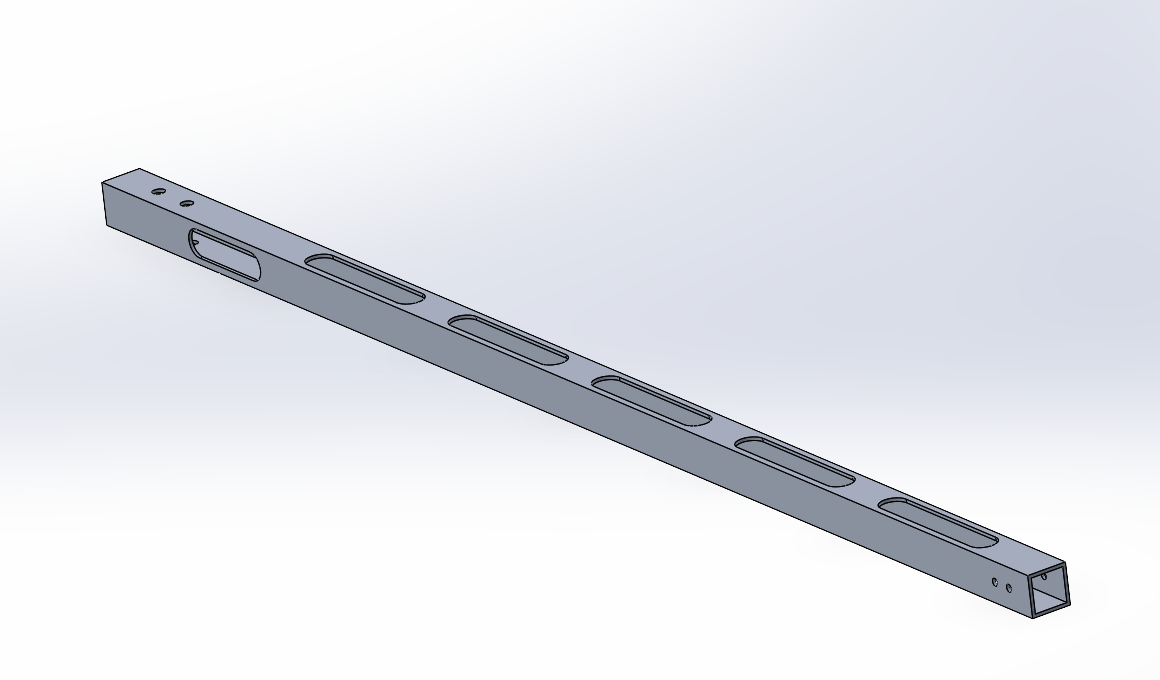
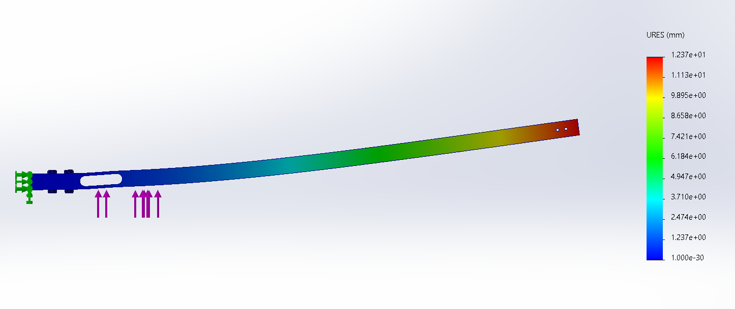
The mounting of the wing spars was not the only analysis that was completed on them. The spars being constructed of boxtube aluminum created a need to conduct weight saving. Slots were milled into the box tube allowing the mass to be decreased by 31%. With the removal of material, the deflection of the spars becomes a greater concern. To get an estimate of the possible deflection, FEA was performed on the spar with 80 N spread across the length of the spar. The deflection was found to be just over 1 mm and the stress was 138 MPa, which is half the yield strength of 6061 aluminum. This gives a safety factor of 2, while under loading which was already given a buffer. Figures 4 and 5 show the spar's geometry and the FEA results.

Figure 4: Geometry of wing-spar with total length of 0.75 meters.

Figure 5: FEA deflection results for spar with exaggerated visual representation.