UAV Payload
October 2023—March 2024
Student Design Team Project
Skills and Technologies:
SolidWorks, Ansys Fluent, Composite Layups, Project Management, 3D Printing, Machining
- Designed an urban air mobility drone’s payload structure in SolidWorks to be capable of carrying 4 passengers and additional cargo while maintaining a lightweight and aerodynamic frame using carbon fiber plates, carbon fiber tubes, and PEEK inserts
- Executed CFD simulations in Ansys Fluent, using a variety of CAD designs to influence design decisions of the cabin shape, adjusting the angles of attack to replicate the many different flying angles of the drone, from 15 degrees to 45 degrees
- Designed a mounting system to allow service to be done to the cabin or drone with more accessibility and less time wasted, while mounting to existing geometry on the drone’s frame that was designed and constructed before the payload requirements from competition
Figure 1: Assembled cabin payload
This project was a part of a student design team's entry for the 2024 Aerial Evolution Association of Canada's student competition. The challenge for 2024 was to design an urban air mobility vehicle designed for efficiency. The payload was deisgned to meet the requirement of carrying 4 passengers, barbie dolls, and their respective luggage. The team's project name was Project Pegasus. To complete this project, a light weight and rigid frame was designed out of carbon fiber panels and tubes, tapped PEEK inserts, and 3D prints. This can be seen in the Figure 2. Heat-set inserts were placed in 3D prints to allow for easy mounting of the payload to the frame of the quadcopter. These 3D prints were also used to attach the aero panels of the payload to the skeleton.
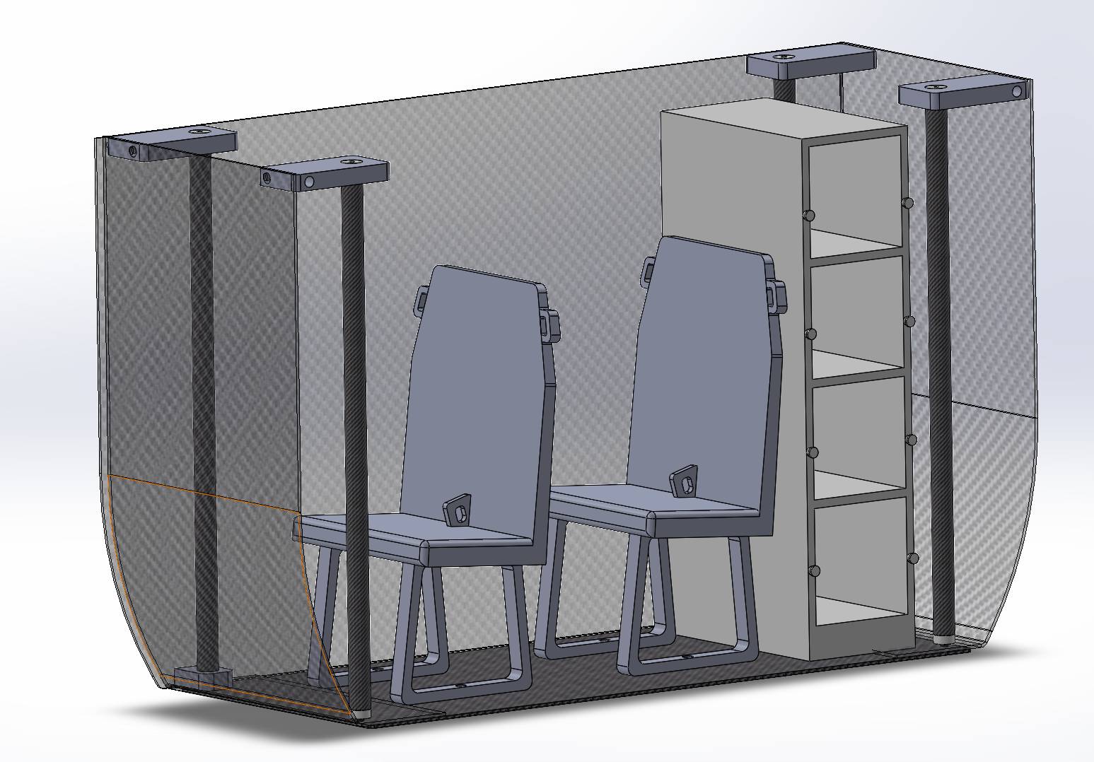
Figure 2: CAD of payload
Designed for efficiency, CFD was used to optimize the external aero panels that were on the payload. However, one constraint was the requirement to mount seamlessly with the quadcopter frame, which was designed prior to the competition requirements. The team is also not experience with complex carbon fiber layups, so complex geometries were not possibly and I would be limited to flat panels. Because of this, the payload was not fully optimized, but was iterated upon to acheive beneficial results for the team.
While completing CFD trials, many different angles were used to mimic the various flight angles of the quadcopter as well as interchanging various designs for the shape of the cabin. The initial shape was prioritized for horizontal travel, but would push air up into the bottom plate of the carbon fiber causing more drag. This original design was tested using CFD simulations in Ansys Fluent. At an angle of attack of 30 degrees, an angle the pilots determined would be most common while flying Project Pegasus. Figure 4 shows CFD streamlines for the 30-degree angle of attack resulting in a drag coefficient of 0.452.
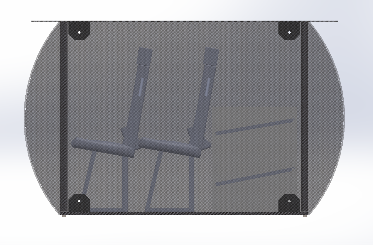
Figure 3: Original shape of payload
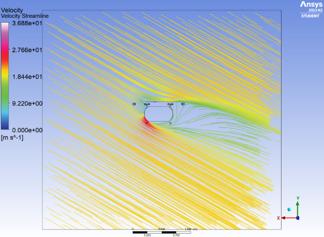
Figure 4: CFD of original cabin shape at 30-degree angle of attack
For the final designs, the payload front and back were designed to be flush with the quadcopter's walls. The shape of the panel was not able to be as optimized due to the requirement of being as tall as the barbie's seated height and the geometry limitations of carbon fiber, but the drag coefficient at an angle of 30 degrees was decreased from 0.452 to 0.215. Over 50% reduction compared to the first iteration.
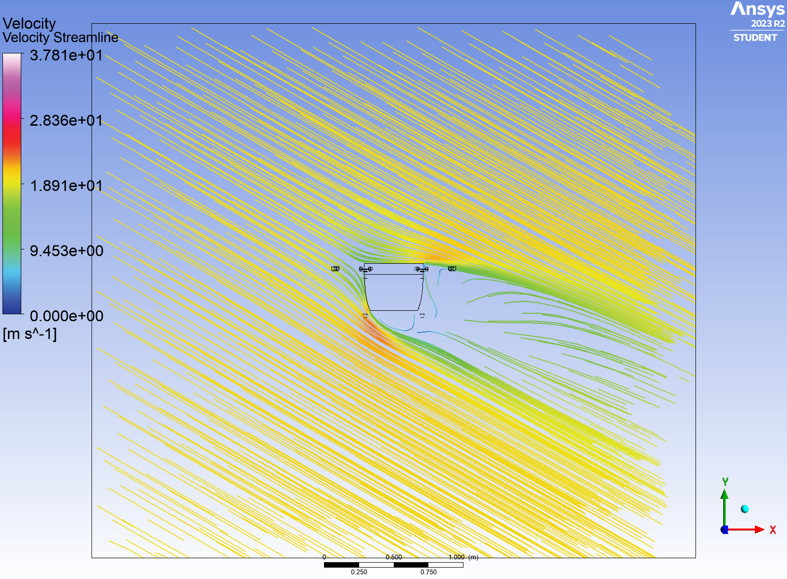
Figure 5: CFD of final cabin shape at 30-degree angle of attack
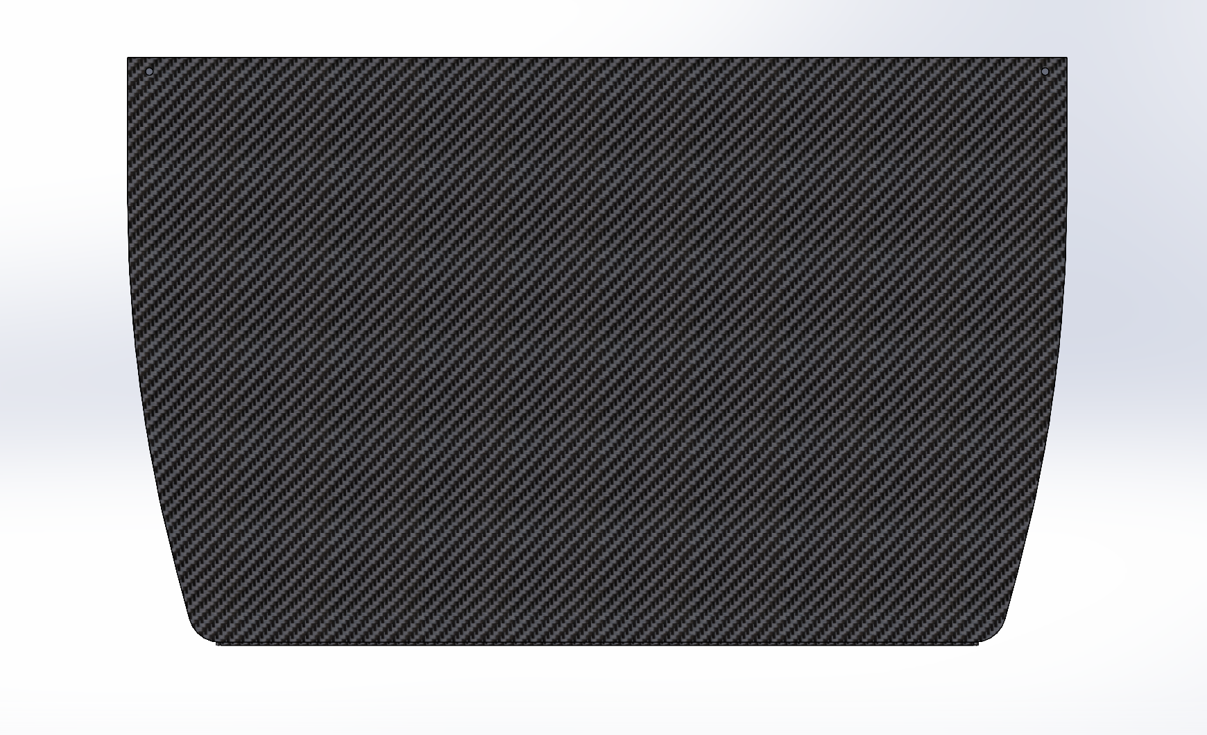
Figure 6: Final shape of payload
Following the completion of the aeropanels' design, integration with the other aspects of the payload was necessary. Seats for the passengers were added, as well as a luggage rack printed out of light weight PLA. The door cut out was made to allow the inside of the payload to be accessed while mounted on the drone, but also to meet the realism requirement from the competition.
Figure 7: Payload mounted to the quadcopter